ObiSolver
The ObiSolver component is arguably the most important component in Obi. It is responsible for simulating particle physics and enforcing constraints. Three important things to remember about solvers:
- They can be added to any GameObject in your scene and there can be more than one solver working simultaneously in the same scene.
- Every actor needs to have a solver up its hierarchy in order to get updated and rendered.
- Each solver is completely independent from other solvers. Therefore, actors being updated by different solver won't interact / collide with each other. Only actors in the same solver will react to each other.
Solvers always perform the simulation in local space. This means that translating, rotating or scaling the solver will rigidly transform the simulation as a whole.
You can inject a percentage of the solver linear/rotational movement back into the simulation, in the form of inertial forces. For instance, you might want to control how much of the overall character movement will affect the clothing simulation. For this purpose, solvers expose two parameters to independently control linear and rotational inertial forces (see below).
Solver
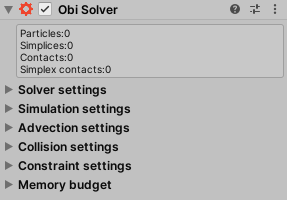
The solver inspector is organized in 4 foldable panels, each one contains parameters affecting one specific aspect of the solver's behavior.
Solver settings
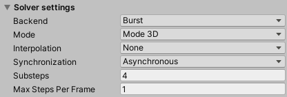
These settings control how the solver works internally:
Backend
Which simulation backend to use. See the backends page for more information.
Mode
The solver can simulate in 2D or 3D mode. In 2D mode, simulation only happens in the XY plane.
Interpolation
Interpolation mode used to render particles. None is faster to calculate, but Interpolate and Extrapolate will give more visually pleasing results. However, they will introduce a 1-frame delay between the actual physical location of particles and the position they're rendered at. Keep this in mind when using interpolation or extrapolation around other objects in the scene. If you have rigidbodies interacting with Obi, it is generally a good idea to use the same interpolation settings for both the Obi solver and the rigidbodies.
- None:
- Results of the last simulation step are directly rendered. Since physics simulation is updated at a fixed frequency but rendering uses a variable frequency, this can result in stutter (specially when the project's timescale is < 1).
- Interpolate:
- Results of the last simulation step and the second-to-last simulation step are interpolated and rendered. This results in smooth motion, but is slightly costlier and causes rendering to be 1 frame behind simulation.
- Extrapolate:
- Results of the last simulation step are extrapolated to the future. This results in smooth motion, but is slightly costlier and causes simulation to be 1 frame behind rendering.
Synchronization
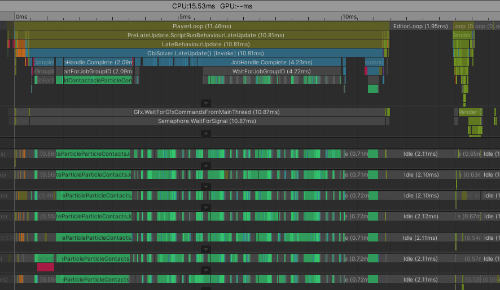
Determines how simulation and rendering are sychronized. In asynchronous mode, the main thread will wait for the current simulation step to finish at the start of the next physics step. This allows physics and rendering to happen concurrently, and unless simulation takes more than one frame to complete the main thread won't be stalled. This yields better performance at the cost of rendering being at least one frame behind simulation.
In synchronous mode, the main thread waits for the current simulation step to finish before rendering the current frame, as a result, physics and rendering happen sequentially. This yields worse performance, but every frame renders the latest available simulation results.
In synchronous fixed mode, simulation kicks off and the main thread waits for it to finish in FixedUpdate(). This yields the tightest integration with Unity's built-in physics. However, it also yields the wost performance out of all 3 methods since it locks the main thread -like synchronous mode- and has the potential to do so multiple times per frame in cases where Fixedupdate() is called multiple times.
See update loop for an in-depth explanation of how Unity's physics update loop works and how the different solver synchronization modes are bolted onto it.

Substeps
How many times to update the simulation during each physics step. This is Obi's main quality vs performance dial: lower substep counts will result in cheaper, faster simulations that look too elastic due to spurious compliance. Higher substep counts will result in costlier, snappier, higher quality simulations.
For an in-depth explanation of how the engine works internally and how substeps affect its output, see simulation.
Max steps per frame
Maximum amount of physics steps can be simulated per frame. Similar to Unity's max allowed timestep, but only affects the solver's simulation instead of all physics in the project.
Simulation settings
Various global simulation parameters regarding external forces/accelerations such as gravity, wind, damping, inertia, etc:

Gravity Space
Whether to apply gravity in the solver's local space (Self) or in world space (World). If set to "Self", the direction of gravity will rotate together with the solver.
Gravity
Direction and magnitude of gravity applied to particles in this solver.
Wind Space
Whether to apply wind in the solver's local space (Self) or in world space (World). If set to "Self", the direction of wind will rotate together with the solver.
Ambient wind
Direction and magnitude of ambient wind applied to particles in this solver. Wind applied by force zones will be added to this base wind value.
Sleep threshold
Any particle with a kinetic energy below this value will be freezed in place. This is useful when you don´t want minuscule variations in velocity or force to perturb an actor, making it look like its jittering or moving very slowly. Set it to zero if you want your particles' positions to be affected by any force that acts upon them, however small it may be.
Max velocity
Particle velocities will be clamped to not exceed this value, limiting how fast they can move.
Max angular velocity
Particle angular velocities will be clamped to not exceed this value, limiting how fast they can rotate.
Damping
Velocity damping applied to particle velocities. Increase it to reduce their kinetic energy.
World linear inertia scale
Controls how much of the world-space linear inertia of the solver transform is applied to the particles. Values range from 0 (none) to 1 (100% of it).

World angular inertia scale
Analogous to the previous property, but controls angular inertia (rotations) instead of linear inertia (translations). Note that centrifugal and coriolis forces are accounted for.
Max Anisotropy
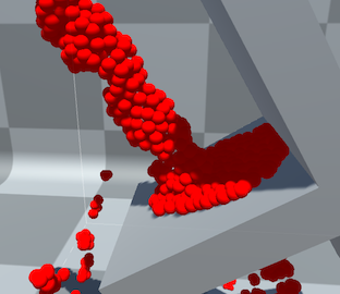
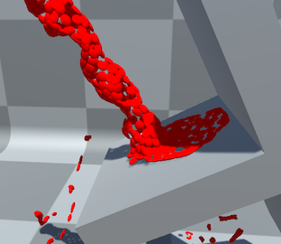
Fluid particles in Obi can be ellipsoidal in shape, instead of perfectly spherical. This is used to better adapt their shape to the surface of the object they represent, achieving more accurate collision detection and smoother rendering. Max anistropy lets you determine the maximum ratio between the ellipsoid's radii: a value of 1 will force all particles to be spherical (deactivates anisotropy), values larger than 1 will allow particles to become more ellipsoidal the higher max anisotropy is.
Simulate when invisible
Should this solver keep the simulation going when invisible to all cameras? Keep this enabled if your simulation needs to be updated at all times, disable it to improve performance when multiple solvers exist in the scene but they are not visible at all times.
Advection settings
These are global settigs that affect all advected particles (foam) in the solver. Check out the page on advection for details.

Foam substeps
Maximum amount of substeps that perform particle advection. Usually a single substep is enough, but it may cause advected particles to not follow simulated particles exactly. For higher-quality simulations or when performance is less of an issue, you can crank up this value to get more accurate advection.
Max foam velocity stretch
Advected particles can stretch along the direction they're moving, this is useful to fake motion blur and gives an extra visual cue to their overall movement. This parameter allows you to control their maximum stretch ratio, 0 being no stretching (1:1 height width ratio), 1 allowing a ratio of 2:1, 2 allowing a ratio of 3:1, and so on.
Foam gravity scale
Advected particles that have very few simulated particles in their neighborhood will follow a ballistic trajectory under the influence of the solver's gravity, simulating spray. This parameter allows you to scale gravity, making it more intense, less intense or even reversing it.
Foam fade
Determines how advected foam particles fade in/out at the start/end of their lives. The slider's left end determines fade in time, and the slider's right end determines fade out time. Fading is performed by modulating the particle's alpha channel.
Foam Accel Aging Range
Solvers preallocate a maximum amount of foam particles (that you can set in the Memory Budget section). When the amount of used/active foam particles goes past a % of the maximum, all foam particles begin to age and die faster. This is an attemp to reduce the amount of used particles and make room for new particles to spawn. The Foam Accel Aging Range determines the minimum and maximum % of used particles that triggers accelerated aging. Up to the minimum %, particles will age normally. At the maximum %, they will age faster according to Foam Accel Aging.
Foam Accel Aging
Aging speed multiplier used when the amount of active foam particles reaches o exceeds the upper range of Foam Accel Aging Range.
Collision settings
These allow you to fine-tune the solver's collision detection pipeline:
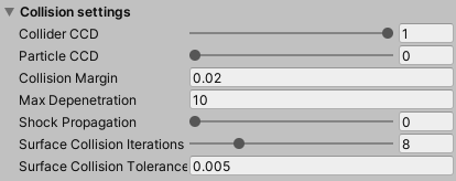
Collider CCD (Continuous collision detection)
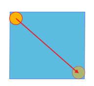
Percentage of rigidbody velocity used to expand collider's bounding boxes during collision detection. A value of 1 will use 100% of the velocity, resulting in full continuous collision detection. A value of 0 will result in purely static collision detection.
Particle CCD (Continuous collision detection)
Percentage of particle velocity used to expand their bounding box during collision detection. A value of 1 will use 100% of the velocity, resulting in full continuous collision detection. A value of 0 will result in purely static collision detection.

Collision margin
Margin added to particle bounding boxes (after CCD expansion), used when generating contacts. Any colliders/particles within the particle's bounding box will be considered for contact generation. This value should be kept relatively low. Large values will generate more contacts, which can improve robustness in very complex scenes, but will negatively affect performance.
Max depenetration
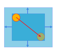
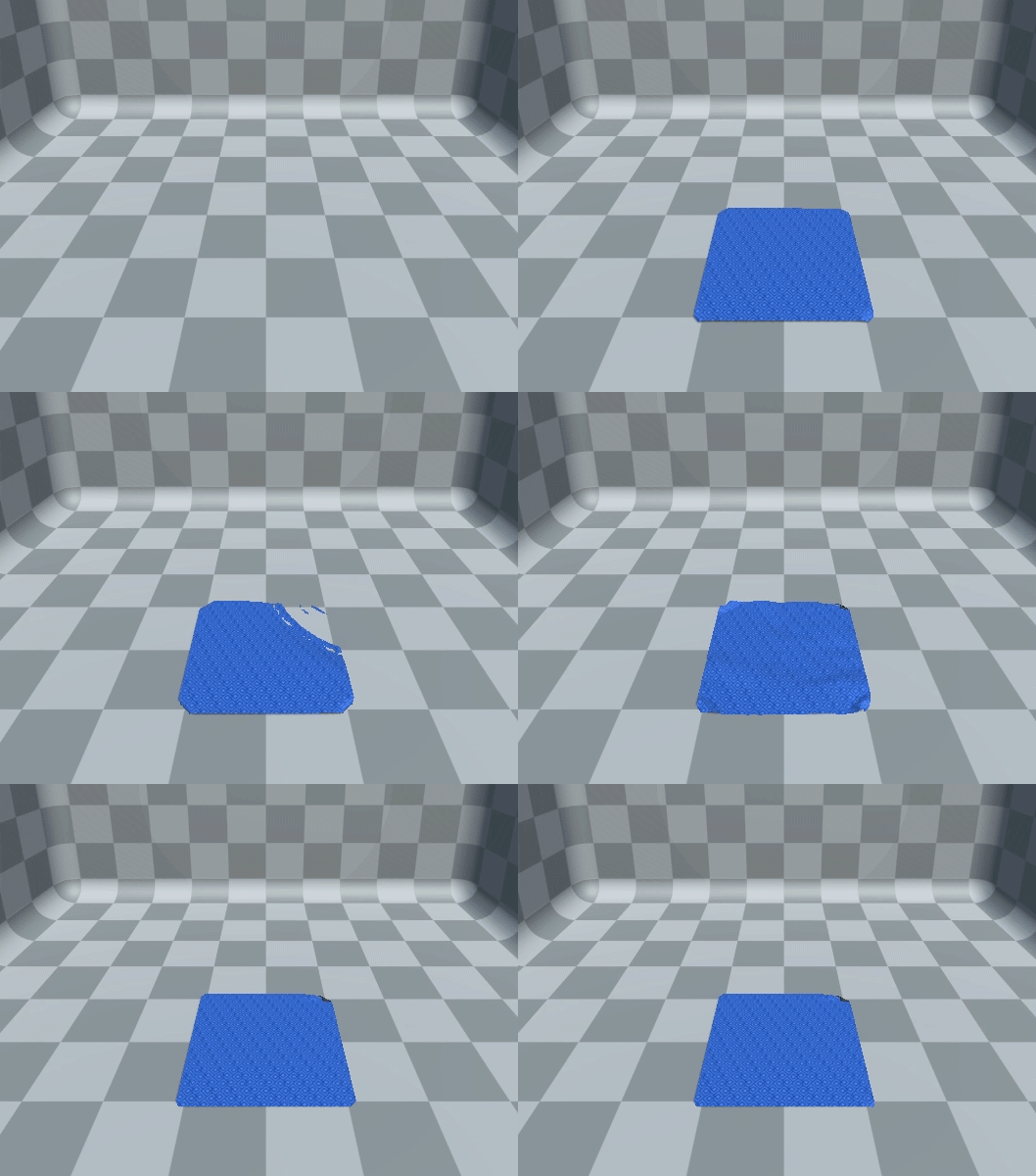
Maximum velocity (in meters/second) applied to particles to take them out of a collider. This only applies to particles that start the physics step already inside a collider. Low values will gently take the particle out of the collider. High values allow the solver to take the particle out immediately, causing it to "jump" out of colliders.
Shock propagation
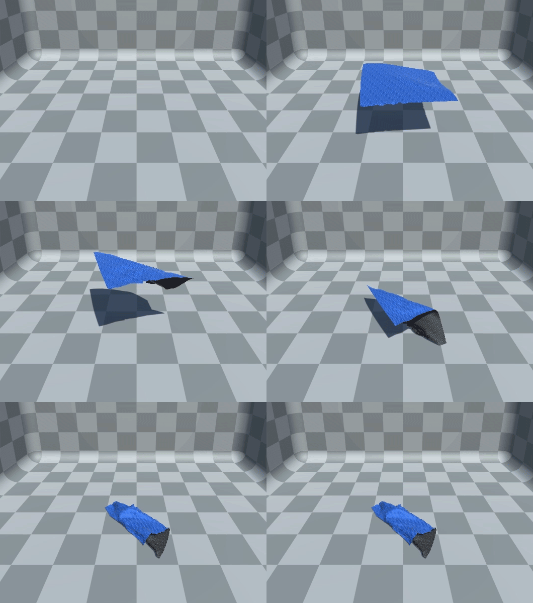
High values will artificially increase the mass of particles supporting other particles. Use it to obtain better stacking stability.
Surface collision iterations
Maximum amount of iterations performed to refine surface collisions.
Surface collision tolerance
Tolerance threshold below which surface collision refinement will stop. Increasing it a bit can help obtain more stable surface collisions against flat surfaces.
Constraint settings
You can globally enable/disable each constraint type for all actors being managed by the solver. Disabling constraints this way (as opposed to disabling constraint components for individual actors) will allow the solver to completely skip any calculations related to that specific constraint type.
For instance, if you disable collision constraints and particle collision constraints, the entire collision detection pipeline is skipped. This allows you to customize what's being done under the hood and get rid of unnecessary overhead.
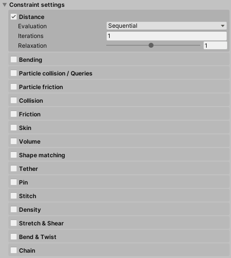
ObiSolver exposes 4 parameters for each constraint type:
Enabled (checkbox right next to the constraint's name)
Are these constraints updated at all? By default all constraint types are enabled, altough this is rarely what you want for production-ready simulations. You should disable any constraints that are not critical for the final look of your simulation.
Iterations
How many times per substep should these constraints be evaluated? A high iteration count will keep the simulation closer to the ground-truth solution. Keep it low if these constraints aren`t very important for your particular purpose and you want to get better performance. The default is 1.
Evaluation mode
Determines how to enforce constraints of this kind. There are two modes:
- In Sequential mode, all constraints are evaluated in the order they were created (which is determined by each specific ObiActor) and each constraint “sees” the adjustments made by all previous constraints. This ensures quick convergence, so your constraints will need few iterations to look good. However it is not very stable when several constraints are fighting for control -it will introduce jittering-, so there are some use-cases where this mode is not a good choice. It is order-dependent, so in low-budget situations (few particles, few iterations and/or large timesteps) this can result in visible patterns in particle arrangement. For those of you a bit on the technical side, this is a Gauss-Seidel type of solver.
- In Parallel mode, all constraints are evaluated but their adjustments are not immediately applied to the particles. Instead, they are stored, averaged, and then the final result is then used to adjust particle positions. This yields a very stable simulation even with lots of constraints applied at once, however more iterations are needed for “hard” constraints as it converges more slowly. It is also order-independent, so it ensures smooth particle arrangements. Use this mode if you want to trade performance -with high iteration counts- or quality -with low iteration counts- for stability and smoothness. Again, for technical users: this is Jacobi-like solving.
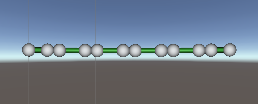
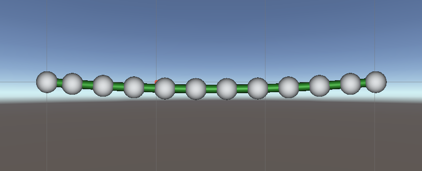
The following images show a rope that's been stretched way past its rest length, using different evaluation modes for distance constraints. In sequential mode (left), a clumping pattern in particle placement caused by order-dependent evaluation is clearly visible. In parallel mode (right) all particles are evenly spaced, but the rope sags a bit more due to reduced convergence speed.
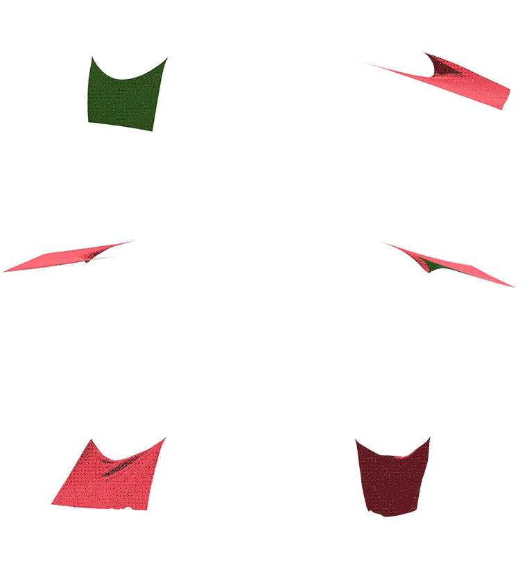
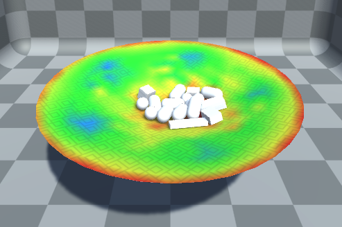
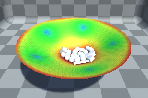
Here's another example: some rigidbodies on a trampoline. Cloth tension is mapped to a color gradient for visualization purposes. In sequential mode (left), tension is unevenly distributed over the cloth's surface, resulting in a noisy color pattern. In parallel mode (right) tension is evenly distributed, but the cloth is more elastic due to reduced convergence speed.
Relaxation Factor
Successive Over-Relaxation (SOR) factor. When trying to satisfy constraints, one way to improve convergence is to “over-relax” the constraints. That is, if moving a particle 2 units to the left would satisfy the constraint for now, why not moving it 3 units? This is exactly what this factor is used for. 1 is the default value, which does not perform over-relaxation at all. 2 is the maximum, which allows you to perform twice as much (200%) relaxation on constraints. High values can be used to help speed up convergence in any of the two modes (sequential or parallel), but keep in mind that simulation stability can degrade. Values lower than 1 will only partially enforce constraints. For instance, with a relaxation factor of 0.25 constraints will only have a 25% of their normal effect.
Memory budget
These settings allow you to control the amount of memory allocated by a solver:
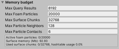
Max Query Results
Maximum amount of results returned by queries on a single frame. Any results that exceed the maximum will be ignored.
Max Foam Particles
Maximum amount of advected particles that can be simultaneously simulated by the solver.
Max Surface Chunks
Amount of preallocated voxel chunks for fluid surface meshing. For more details, see fluid rendering.
Max Particle Neighbors
Amount of memory allocated to store the indices of neighbor particles for each fluid particle.
Max Particle Contacts
Amount of contacts against colliders or other particles each particle can have.