Character bones
Obi can be used to simulate character appendages and certain body parts. This includes things like braids, breasts, tails, etc. but is not limited to this: you can add physical simulation to any bone hierarchy by adding a ObiBone component to it.
Bone hierarchies endowed with ObiBone become part of an animation-driven physical simulation: they will react to gravity, external forces, character movement/inertia, collisions against other objects, etc. The following animations show a dragon's tail (made of 12 particles, weighting 144 kg in total) driven by both animation and simulation using ObiBone:
How to set it up
The typical use case for ObiBone is to drive character bones. This means two things:
- The ObiSolver component should almost always be placed at the character's root. This ensures simulation happens in character space, and gives you fine control over inertial forces.
- Animation and simulation must happen in a specific order each frame: animation first, simulation second.
To ensure animation happens before simulation, you can either:
- Use a ObiLateUpdater component to update the simulation and set your Animator's update mode to "Normal".
- Use a ObiLateFixedUpdater component to update the simulation and set your Animator's update mode to "Animate physics".
If you're unsure about update order, check Unity's execution order chart. Once both your solver and your updater are in place, you can add a ObiBone component to any bone in your character by using Unity's "Component" menu: Component->Physics->Obi->Obi Bone. This is how its inspector window looks like:
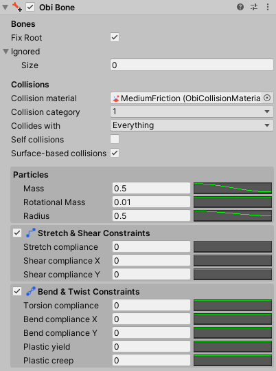
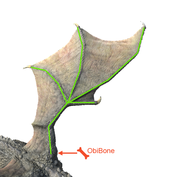
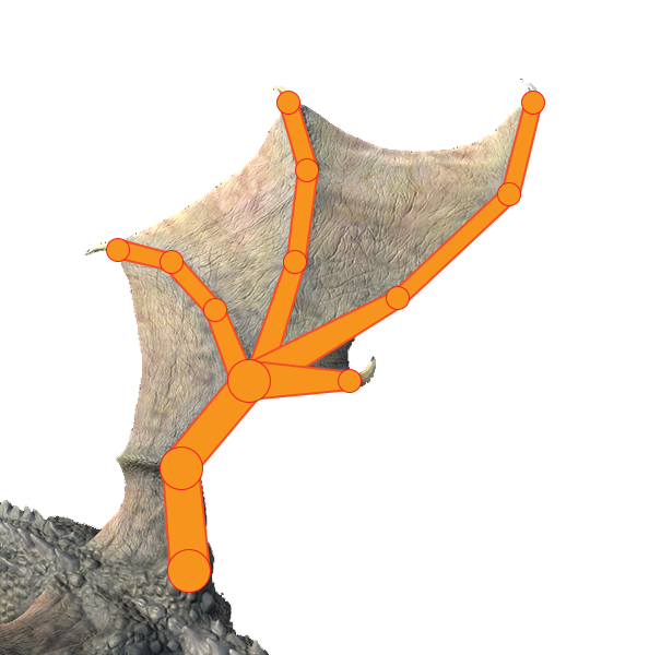
This component will create a particle for every bone down its hierarchy in a recursive fashion -starting from the bone transform it has been added to, which will be referred to as its root bone-, and rig them up using constraints. The bone that's furthest away from the root bone (measuring distances from each bone to the next) is known as the tip bone.
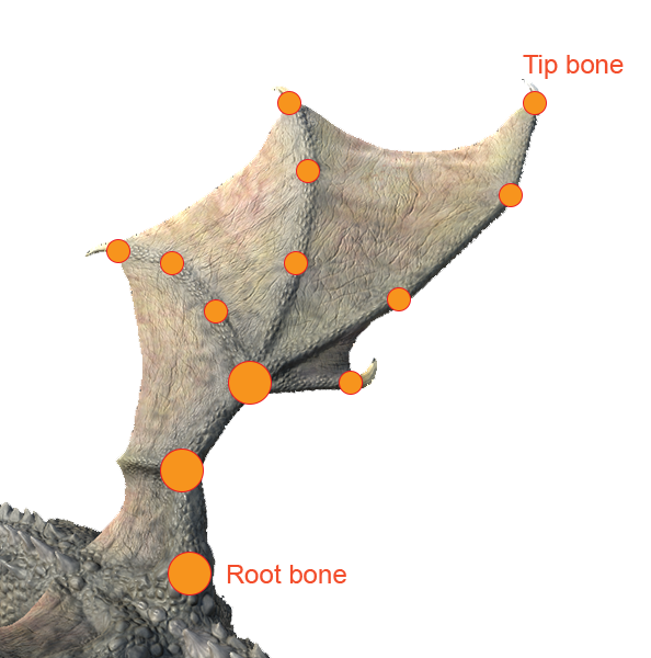
Let's take a look at each parameter:
Fix Root
When enabled, the root particle will copy its position and rotation from the root bone. This is usually what you want for character appendages, so it's enabled by default. If you want the root hierarchy to be able to freely move around instead, disable this option.
Stretch bones
When enabled, bones will copy particle positions, which means they will stretch and shear together with particles. Disable it to only transfer particle rotation to the bones.
Ignored
You can exclude specific bones or entire branches from the ObiBone components.
Collision Material
Material used to resolve collisions. See collisions.
Collision category
Category used by this bone hierarchy. See collisions.
Collides with
Categories this bone hierarchy is allowed to collide against. See collisions.
Self collisions
If enabled, this bone hierarchy will be able to collide with itself.
Surface-based collisions
Enables surface-based collisions for this bone hierarchy. See surface collisions. When using surface collisions, the entire bones (instead of just particles) are used for collision detection. Use this if the spacing between bones is very large in your skeleton and you need accurate collision detection.
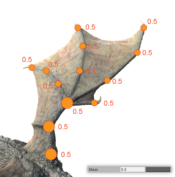
Curve attributes
The following attributes can vary spatially along the bone hierarchy. You can specify both a base value and a distribution curve for each one of them. The final attribute value at each bone in the hierarchy is determined by evaluating the curve at each bone's normalized position -which ranges from 0 at the root bone to 1 at the tip bone- and multiplying the resulting percentage by the base value. See the following diagram:
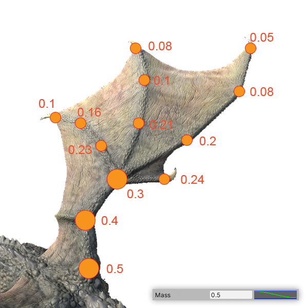
Mass
Mass for each particle in the bone hierarchy. The mass of a particle determines how it reacts when interacting/colliding with other particles. Heavier particles can easily move comparatively lighter objects.
Rotational Mass
Rotational mass for each particle in the bone hierarchy. The rotational mass of a particle determines its rotational inertia: particles with higher rotational mass are more difficult to rotate and once rotating, will keep rotating on their own for longer. Particles with a small rotational mass rotate easily and their rotation feels more "snappy".
Radius
Radius for each particle in the bone hierarchy. This determines the size of each particle.
Stretch compliance
Stretch compliance for each constraint in the bone hierarchy. See stretch/shear constraints.
Shear compliance X
Shear compliance in the X axis for each constraint in the bone hierarchy. See stretch/shear constraints.

Shear compliance Y
Shear compliance in the Y axis for each constraint in the bone hierarchy. See stretch/shear constraints.
Torsion compliance
Torsion compliance for each constraint in the bone hierarchy. See bend/twist constraints.
Bend compliance X
Bend compliance in the X axis for each constraint in the bone hierarchy. See bend/twist constraints.
Bend compliance Y
Bend compliance in the Y axis for each constraint in the bone hierarchy. See bend/twist constraints.
Plastic yield
Plastic yield for each constraint in the bone hierarchy. See bend/twist constraints.
Plastic creep
Plastic yield for each constraint in the bone hierarchy. See bend/twist constraints.