Rope/rod blueprints
In this page we will learn to generate and edit rope and rod blueprints. Each one has a matching actor type.
- Rope:
- Ropes are built by chaining particles using distance and bend constraints. Since regular particles have no orientation (only a position), torsion effects cannot be simulated (wikipedia), and ropes cannot retain its rest shape. However, unlike rods, ropes can be torn/split and their length can be changed at runtime.
- Rod:
- Rods are built by chaining oriented particles using stretch/shear and bend/twist constraints. They are much more sophisticated than ropes, can simulate torsion affects and retain their rest shape. However, their length cannot be changed at runtime and they cannot be torn/split. Rods are ideal to model springs, thick bars, antennae, etc.
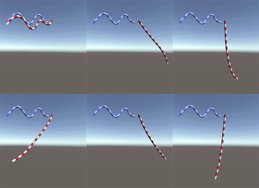
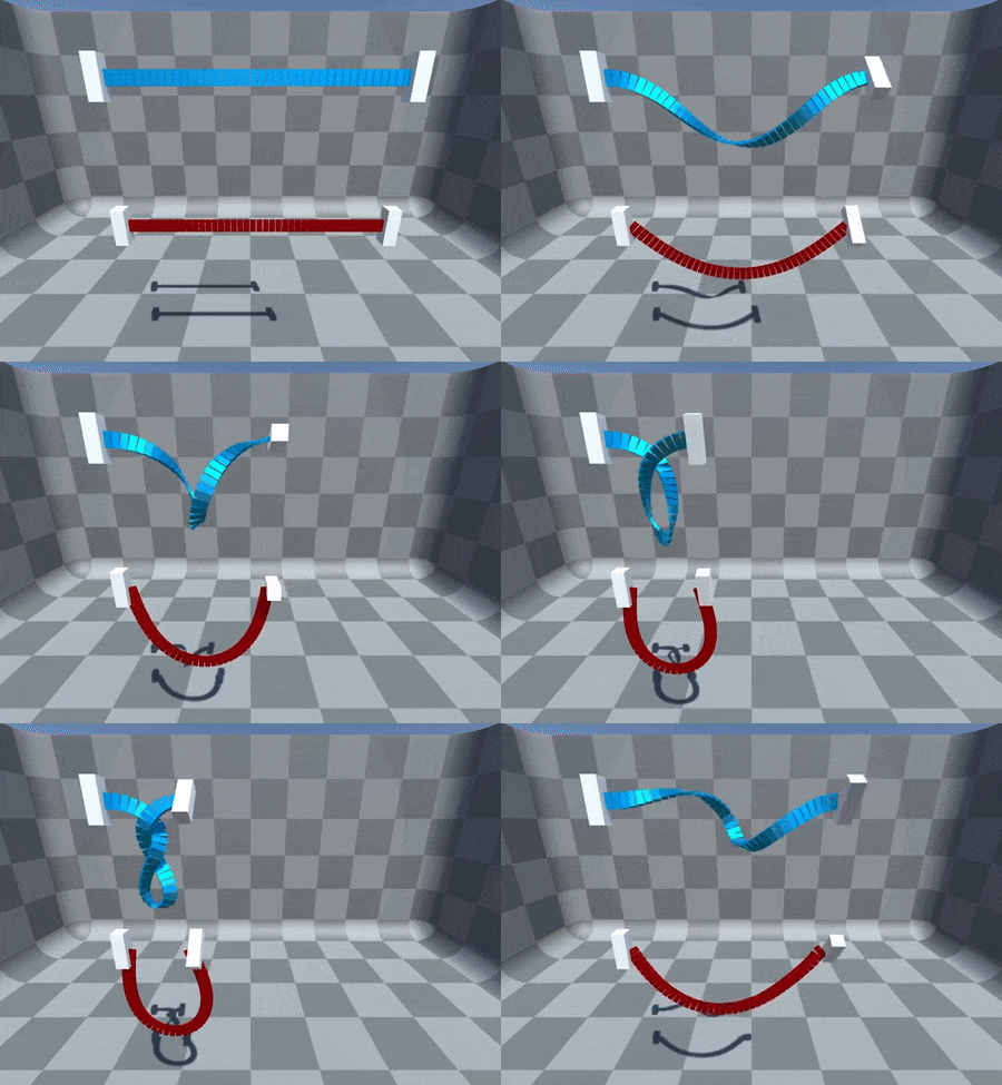
Unlike ropes, rods cannot be torn or dinamically resized. This table sums up the key differences between ropes and rods:
| feature | ObiRope | ObiRod |
|---|---|---|
| Rest shape | No | Yes |
| Torsion resistance | No | Yes |
| Dinamically resizable (ObiCursor) | Yes | No |
| Tearable | Yes | No |
To generate a basic rope/rod blueprint, go to Assets->Create->Obi->Rope/Rod blueprint, or right-click on a project folder and select Create->Obi->Rope/Rod blueprint. Rope and rod blueprints have the following parameters:
- Thickness:
- Radius of the particles used to generate the rope/rod, expressed in meters.
- Resolution:
- Density of particles per length unit. A value of 1 will generate particles with an overlap equal to the rope thickness. A value of 0.5 will generate particles in such way that they barely touch each other. Values lower than 0.5 will leave gaps between particles, which can be detrimental to collision detection robustness but beneficial for performance. A value of zero will only generate one particle per control point.
Internally, the formula used to calculate the amount of particles in the rope based on resolution is: particleCount = ropeLength / ropeThickness * resolution. If you're creating ropes at runtime, you can use this formula to calculate the required resolution to get a specific amount of particles in the rope: resolution = particleCount / (ropeLength / ropeThickness).(In the lower resolution rope, bend and distance constraints can be seen as faint purple and green lines.)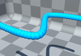
Resolution: 1 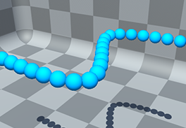
Resolution: 0.5 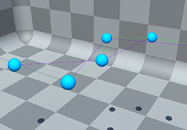
Resolution: 0.1 - Pooled particles:
- (Ropes only). Extra particles allocated to be used when tearing or resizing the rope. You can set this value to zero if you do not plan on tearing or resizing the rope at runtime, as no extra particles besides the initial ones will be needed.
- Keep initial shape:
- (Rods only). Enable this if you want the rod to keep its initial shape as its rest shape. Disabling it will cause the rod to assume a completely straight rest shape.
To edit a rope or rod blueprint, assign it to the blueprint slot of a rope or rod actor. Then, click the edit path button to enter path edit mode:

Path editor
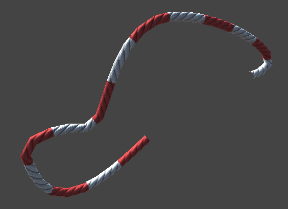
Particles in the rope/rod blueprint are generated along a path (a.k.a spline), which is a curved shape passing trough several control points.
In the path editor you can add/remove control points, move/rotate/scale existing control points, and set per-control point properties that will be interpolated to the rope's particles. While editing the path, you will have instant feedback of what the resulting rope/rod looks like.

Editing control points
Click on a control point to select it. You can add control points to the current selection by holding "shift", you can also drag a selection marquee around them. Clicking on an empty screen area to deselect all control points. Translate, rotate and scale gizmos work in the same way as they do with regular GameObjects, so do the pivot and transform space toggles.
Each tangent handle has three modes of operation, which can be set per-handle: Free, Aligned, or Mirrored.
- Free
- Each half of the handle is free to move independently. This allow to create sharp corners or sudden changes in curvature.
- Aligned
- Both halves will be forced to lie in the tangent to the control point, however their length can be set independently.
- Mirrored
- Both halves will be forced to be identical, both in direction and length.
In addition to the tangent mode, each control point has several properties that are passed on (via interpolation) to the particles:
- Thickness
- Thickness of the rope at that point. Interpolated to particles, used for collision detection and rendering.
- Mass
- Particle mass. Determines how the particle behaves when involved in any constraint (collision, distance, bending...) with another particle or a rigidbody.
- Rotational Mass
- (Rods only): Particle rotational inertia tensor. Determines how difficult it is to rotate particles: the higher the mass, the more difficult it is. This has a direct effect on how rigid the rod feels.
- Category:
- Particle collision category, used to determine when collisions with colliders and other particles should be ignored. For an in-depth explanation, see collisions.
- Collides with:
- Particle collision mask, used to determine when collisions with colliders and other particles should be ignored. For an in-depth explanation, see collisions.
- Color
- Color of the control point, interpolated to particles. This color is passed to the mesh vertex colors when using a ObiRopeExtrudedRenderer.
- Name
- Obi will automatically create one particle group for each control point, containing the particle closest to that control point. You can set the name of the group here. When using ObiParticleAttachments to attach the rope, the names you set here will be listed in the attachment's particle group dropdown, allowing you to select which point of the rope to attach.
Translate/Rotate/Scale control points tools


These tools allow you to translate/rotate/scale the selected control points, they're similar to Unity's translate/rotate/scale transform gizmos.
Add control points tool
This toggle enables a tool to add control points to the spline visually. A green dotted line will appear between the mouse cursor and the closest point in the spline. Clicking will insert a new control point in the curve at that position.
Remove control points tool
This toggle enables a tool to remove control points from the spline visually. A red dotted line will appear between the mouse cursor and the closest point in the spline. Clicking will delete the closest control point in the curve.
Open/close path
A path can be either open (both ends are independent) or closed (the curve follows a closed path, with both ends sharing the same position and tangent).
Orientation tool (rods only)
This tool allows you to define the orientation of each control point. This lets you specify the rest twist of the rod.
Toggle tangent handles
Toggles tangent handles on/off.
Toggle thickness handles
Toggles thickness handles on/off.