Cloth blueprints
In this page we will learn to generate and edit cloth blueprints.
There are 3 different cloth blueprint flavors, each one specifically designed for a purpose. Each one has a matching actor type.
- Cloth:
- Regular cloth. Cannot be torn, cannot be used with animated meshes. This is the most efficient of the 3.
- Tearable cloth:
- Can be torn, cannot be used with animated meshes. This tearing capability has an associated memory and runtime cost.
- Skinned cloth:
- Designed to be used with skeletally animated meshes for character cloth, cannot be torn.
To generate a basic cloth blueprint, go to Assets->Create->Obi->Cloth blueprint, or right-click on a project folder and select Create->Obi->Cloth blueprint. The other 2 blueprint types can be created in a similar way.
Generating a blueprint
Cloth blueprints take a mesh as input. Due to the internal data structures used to represent cloth, input meshes must be 2-manifold. Non-manifold features are not supported, and while Obi will try to make things work anyway, chances are using non-manifold meshes will give quite some trouble down the pipeline, so try to avoid them.
Also, meshes must be readable, so make sure the Read/Write enabled checkbox is marked in the mesh import settings. See Unity's manual for more info.
When you press the Generate button in the blueprint inspector, this is what Obi does:
- Generate a list of merged mesh vertices, ignoring uv and normal seams.
- Generate a list of merged triangle edges and border edges.
- Generate one particle per merged vertex, and one distance constraint per merged egde.
- Analyze the resulting particle/distance constraint network to generate bending, volume, and aerodynamic constraints.
- Sort and group all constraints into batches for efficient runtime evaluation.
This process can take quite a while. Once it is done, the Edit button will activate. Pressing it you will enter the cloth blueprint editor.
Cloth blueprint editor
There's three main modes in the cloth blueprint editor, that can be acessed using the 3 buttons at the top:
- Particle selection
- Property painting
- Texture import/export
Particle selection
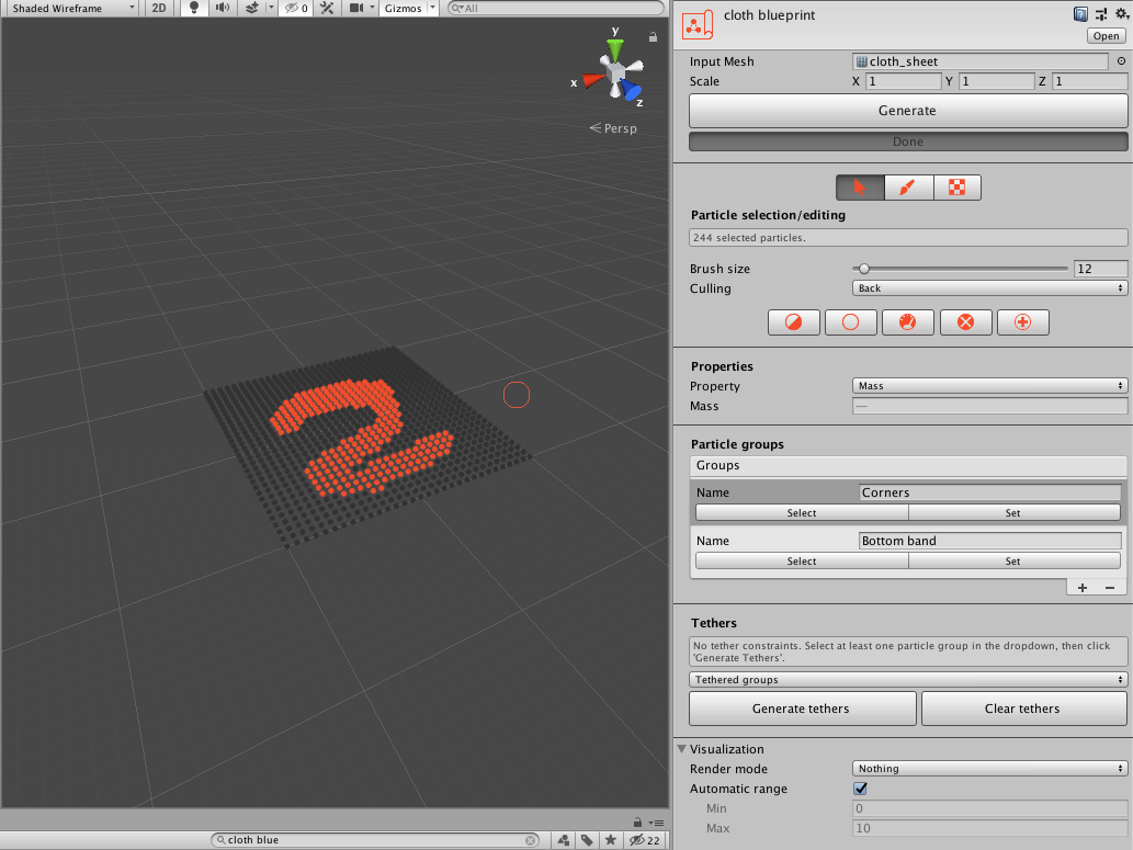
Selection/editing
In particle selection mode, you can select particles to modify their properties, create particle groups, and generate tethers. To select particles, click and drag over them in the scene view. To deselect particles, hold the shift key while dragging.
You can change the brush size by dragging the brush size slider. You can change the particle culling mode to one of three options:
- Off:
- All particles will be drawn and selectable.
- Back:
- Particles facing away from the camera won't be drawn nor selectable.
- Front:
- Particles facing towards the camera won't be drawn nor selectable.
There's also a few available tools that operate on the current selection:
- Invert selection:
- All particles will be drawn and selectable.
- Clear selection:
- Particles facing away from the camera won't be drawn nor selectable.
- Optimize selection:
- Delete all selected particles that share no constraints with any unselected particle. This is useful when you intend to attach a group of particles to a transform, and want to get rid of those that won't contribute to the simulation after being attached.
Prior to optimization. 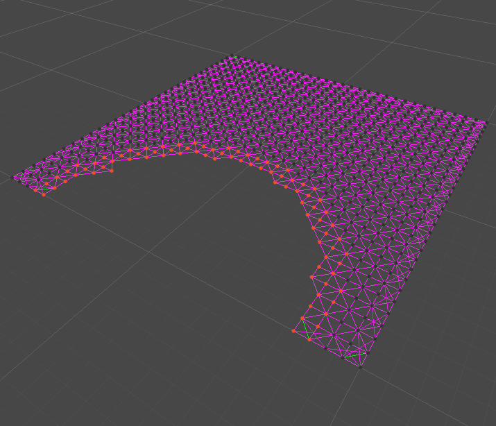
After optimizing the selection, only selected particles that share constraints with unselected ones remain.
- Remove selection:
- Delete all selected particles.
- Restore removed:
- Will bring back all particles deleted as a result of optimization or removal.
You can get/set any property of the currently selected particles:
- Mass:
- Particle mass. Determines how the particle behaves when involved in any constraint (collision, distance, bending...) with another particle or a rigidbody.
- Radius:
- Particle radius. Mainly used for collision detection.
- Category:
- Particle collision category, used to determine when collisions with colliders and other particles should be ignored. For an in-depth explanation, see collisions.
- Collides with:
- Particle collision mask, used to determine when collisions with colliders and other particles should be ignored. For an in-depth explanation, see collisions.
- Color:
- Particle color. Useful to store additional info, or to be used in custom rendering.
Particle groups
You can group together particles that have a special role or significance to you. For instance, you could create a group out of the 4 particles at the corners of a rectangular cloth sheet, to be able to later hang it from another object. Groups are mainly used when creating particle attachments, but can also be acessed at runtime in custom scripts.
To create a new group from the current selection, simply press the "+" button at the bottom right corner of the list. To delete a group, select it from the list and click "-". You can also select all particles in the group by clicking the select button (multi-selection of groups using the shift key also works), and you can replace the particles with the current selection by clicking set.
Tethers
Tether constraints prevent particles in the cloth from separating from other particles, far away from them, acting as long-range distance constraints. They are generally used as a cheap way to minimize unwanted stretching in low-budget simulations.
To generate tethers, select one or more particle groups from the dropdown list, and click Generate tethers. This will tether all particles that aren't in any of the groups, to the closest particles in the groups. To delete all tethers, click Clear tethers.
Visualization
All three blueprint editor modes (selection, painting and texture import/export) have a visualization options section. Here, you can change the render mode which determines the elements that should be drawn in the scene view. Some of the options are:
- Nothing:
- Only the particle selection handles are rendered.
- Everything:
- All render modes are enabled at once.
- Particles:
- Particles are fully rendered, showing ther shape, size and color. This uses the same render pipeline as the ObiParticleRenderer runtime component (see particle rendering)
- Mesh:
- The source mesh used to generate the blueprint is rendered. The currently selected particle property is used to drive vertex colors. You can use the range options in the visualization section (see below) to determine how property values are mapped to colors.
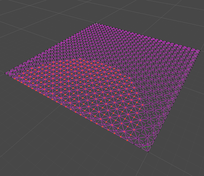
- Constraints:
- Multiple constraint render modes let you visualize the constraints in your blueprint.
When the mesh render mode is active, the currently selected property (mass, radius, etc...) is mapped to a color gradient and used to draw the mesh. By default, the minimum and maximum property values are calculated and used to map values to a color gradient.
Property painting
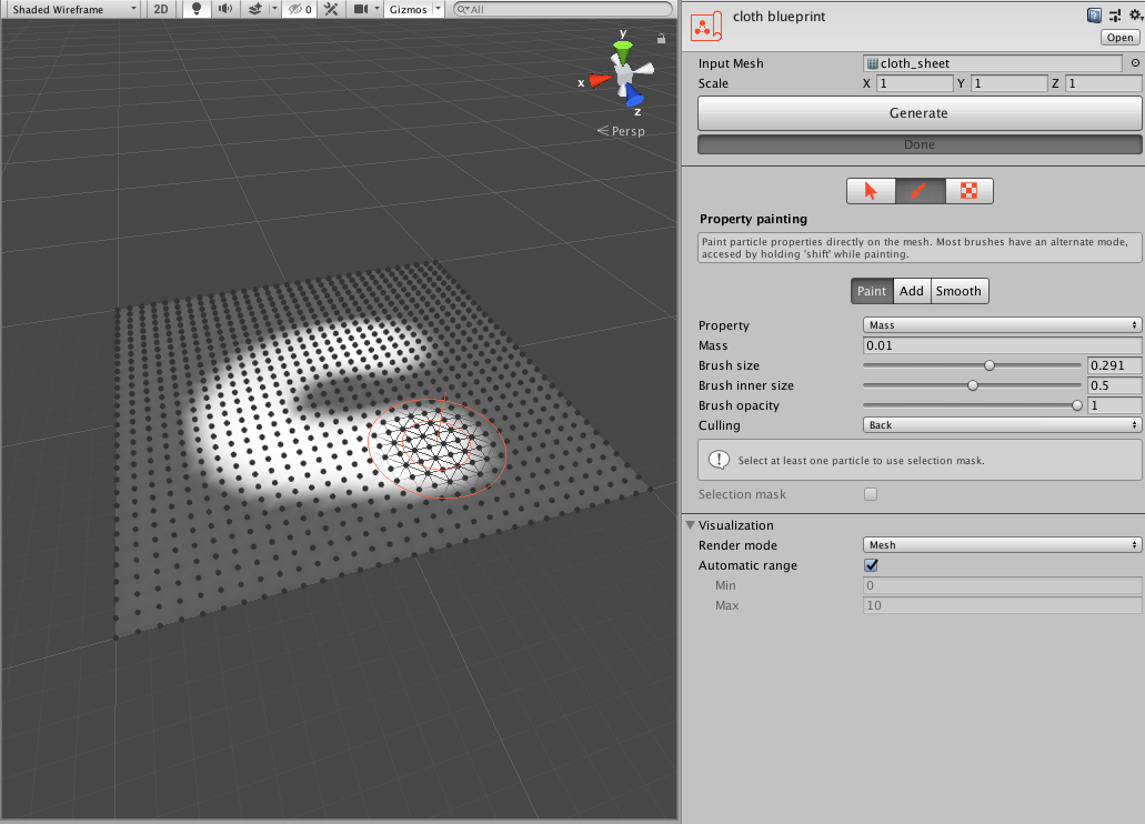
In property painting mode, you can use brush tools to paint particle properties directly on the surface of the cloth. Enabling the mesh render mode is recommended to work when painting.
The brush has a inner and an outer radius. The brush opacity within the inner radius can be set by changing the brush opacity value. The opacity smoothly decays outside the inner radius, reaching zero at the outer radius.
Most properties offer 3 brush modes:
- Paint:
- Displaces the current property values towards the one set in the proprerty field. The brush opacity determines the speed at which the values shift towards the target one.
- Add:
- Adds the value set in the property field to the property values in the mesh. Again, the brush opacity determines the speed at which the values are changed. You can hold shift in the keyboard to subtract instead of add.
- Smooth:
- Smooths out the property values.
Selection mask
If there are some particles currently selected, you can enable selection mask. When the selection mask is active, the paint brush will only act upon the selecte particles. This is useful if you only want to paint some parts of the mesh.
Texture import/export
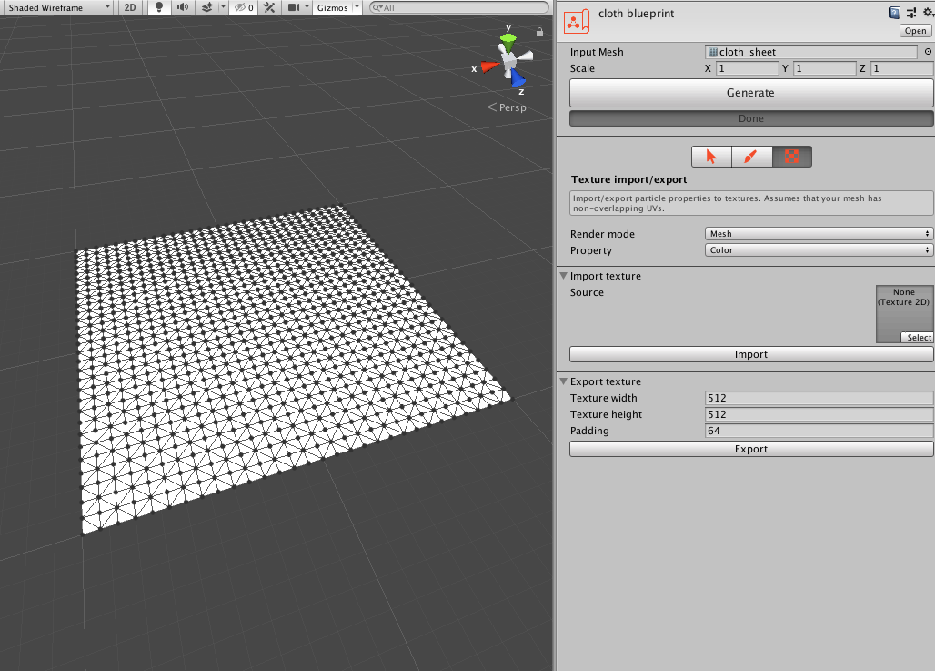
You can import/export any property to a texture using these tools.
Import
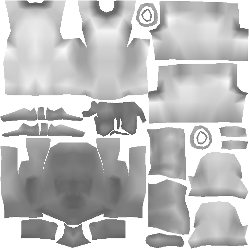
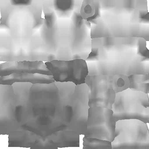
When loading property values from a texture, we need know how to map pixel values to property values. Obi maps linearly from the 0-255 pixel value range to a user-defined property value range.
- Source:
- Texture used to read property values from.
- Source channel:
- While some properties (such as color) use up all 4 texture channels (red, green, blue and alpha), most properties (mass, radius...) are floating point values, so only one texture channel is needed to store/retrieve them. Using this dropdown you can select which channel to read values from.
- Min value:
- Property value read from pixels with a value of 0.
- Max value:
- Property value read from pixels with a value of 255.
Export
When exporting color properties, all 4 texture channels are used. When exporting floating point properties, the maximum property value in the mesh is mapped to white pixels (255) and the minimum value to black pixels (0). Values are always stored in the red texture channel.
- Texture width:
- Width of the texture in pixels.
- Texture height:
- Height of the texture in pixels.
- Padding:
- Amount of pixel padding added around UVs seams. Ensures accurate values are read at the UV seams when importing values back from the texture.